Sunday 28 March 2010

A new Central Crank Web and Big End Journals

On examination of the old assembly it appears the screw pin location hole was drilled and reamered on the p***. I don't know how I managed that, hence the resulting stress fracture. So, back to the drawing board to make a new one.


Jig set up for silver soldering the big end journals into place.


The new Central Web complete with Big End Journals

The journals are too long at the moment and will have to be cut to length to enable fitting between the front and rear crank webs.

I removed the shaft from the gear box because the bearing was lumpy, but it worked fine after I'd taken it out, so I cleaned it all up and noticed the shaft was bent. This could be the cause of the lumpyness, so shaft straightened and re-assembled into housing, it now works fine again.

Monday 22 March 2010

Disaster!

I tried to fire up the KT120fsT today, and with very poor results. I managed to get it firing on one cylinder and occasionally it attempted two, but that is as far as things went. It all ended in tears when suddenly things came to an abrupt halt. I couldn't turn the crankshaft through a full 360, there was a stop preventing it going any further. Time to pack it all in and have some tea.

Broken crank pin

After tea I began dismantling the engine and it wasn't long before I discovered the crank pin on the central web had severed. I've also noticed the other pin in the web is loose. I must have done a poor soldering job there. Nothing else in the engine is damaged although the bearing in the gear box housing is a bit lumpy. I think I will change it.

A sorry sight

Sunday 21 March 2010

Nearly finished

Yes, its almost ready to be fired up. Just a few odds and ends to finish off. Loads done today, I was hoping to position the carburettor on top of the engine, but there isn't quite enough space inside the cowling so plan "B" takes effect and the carb is mounted under the engine mount, between the exhausts.


View of the front underside

The carb is mounted with a 4.5mm offset. This is to compensate for the differing lengths of delivery tube. (They are different due to the 9.0mm cylinder offset.) The 4.5mm offset makes the mixture transit distance equal to both port and starboard cylinders.

Temporary fitting to the firewall


View of the rear with mount removed to show delivery tubes

The delivery tube system is made from 10mm micro bore tube and two standard elbow fittings. These fittings were modified to remove the solder ring and to add lightness. The two joints either side of the carb are butt joints. All the joints on the delivery tubes are silver soldered and there is a spigot silver soldered to the main part which extends into the carburettor manifold and the aluminium adaptor is glued to the spigot using Loctite 603 oil tolerant retainer. The carburettor is held in place using two M3 grub screws.

I can hear it running already!


Saturday 13 March 2010

Made light work of more progress

Placed some strategic holes in the base plate to add lightening. They were designed for position and size, in other words not randomly placed.


Lightening holes (Not lightning holes)

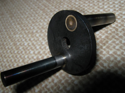
I also made the exhaust pipes, large in diameter to muffle the bark. Aluminium inserts are pressed into each end of a stainless steel tube and the assembly is screwed to the cylinder head using an M3 socket cap head screw.

Exhaust stacks fitted


I've just looked back through my blogs and discovered that I started building this engine late in 2008

I went flying today as the forecast was good and with light winds. 'Tiz different when you get there, it was good earlier but the wind got stronger for the North West and by lunch time it was really cutting and Ipacked up and went home. Not before flying the Sunbeam and the Pico-Jet, and on the second flight with the Pico-Jet the prop parted company with the motor. All the bits flew off and scattered on the runway - time to land.

Phil was there with his Funtana. Look at the kit he's got to charge the batteries. That's not all, there's also a generator to power it all up.

No less than FOUR chargers


Phils Funtana

Exit left

Sunday 7 March 2010

Engine Mount and First Trial Fitting

Started and finished the engine mount, and fitted it to the Ultimate to see how well it fits. The pictures tell more:-


Bags of room inside - Could've built a bigger engine


Exposed, showing the mount.


6mm dia. base, 8mm dia. spacers tapped M4 both ends


4 Degree angle


The original holes in the firewall are drilled at a 4 degree angle. This is to accommodate a large two stroke engine with a larger diameter cylinder and designed to fully enclose it so that unsightly holes don't need to be cut in the cowling. The KT120fsT needs to be horizontally mounted so the plate needed to be adapted.

Base is made from cast plate for lightness


So far it weighs 670 grammes including the mount, thats 1lb 7.5oz in old money. Not bad for a home build 24cc twin. There's a bit more to add, carburettor, manifold and delivery tubes, and exhaust pipes.


Monday 1 March 2010

Things are beginning to get exciting...

Getting very close to the day when I can put some fire in its belly. I have to say, I'm very pleased with the way its turned out so far, there's been some difficulties, but I've designed my way out of them. All that's left to do now is make a pair of exhausts, the inlet manifold, mount the carburettor and make an engine mount suitable for the Ultimate Bi-plane.

Here's some pix:-

Gearbox cover detail


Starboard cylinder head close-up


Prop driver assembly fitted


Full view of the rear (top)


Underside