Saturday, 24 April 2010

Another Crankshaft Failure

Yes, it failed again. This time it twisted slightly which meant the pistons didn't reach top dead centre at the same time, and the central crank web was rotating eccentrically in the crank case. This also meant the valve timing had slipped and the pistons were just hitting the valves of one cylinder. Luckily no damage was done, and now I've decided to manufacture a one piece crankshaft and the material arrived this week. Its a good job I made the crank case with a bulge in both sides as I'm going to need that internal volume for the much larger two-part big ends of the conrods. The material is an alloy steel, EN16T which is a tough steel, good with torsional strength. The down side of all this is that (as I mentioned earlier) I have to make two new conrods with a split big end and a split bearing. This bearing is made by soft soldering two pieces of phosphor bronze together and turning the bearing as one piece, then heating it up to melt the solder to form the two big end shells.
To give you an idea of the size, the cutter in the photo is 6.0mm diameter.

Crankshaft during remanufacture


Saturday, 10 April 2010

Best day for flying so far this year

Wall to wall hazy sunshine and light winds from the East. I thought it best to go today as the weather for tomorrow (Sunday) is breezy. Took the Pico-Jet, Sunbeam and the Yak and actually plucked up the courage to fly it. Had an engine cut shortly after take off, despite extensive pre-flight testing. The next flight was OK, but I had to stop to video this:-

Ians F16 is always an impressive display.

Two flights with each aircraft today, and I brought them all home in one piece - a very satisfying day.

Thursday, 1 April 2010

No April Fool

So this blog is about yesterday. (Wednesday 31st March 2010).


I've managed to re-assemble the KT120fsT and fit it to the fuselage of the Ultimate. I packed it all into the car and took it to work because at 19:00hrs the factory hooter goes off and I shout "Yaba Daba Doo"! (Flintstones connection) and then its time for a quick sprint over to the George Inn at Middlezoy to enter the Sedgemoor Clubs' Craftmans Cup. This is a chance to see what club members get up to in the cold dark Winter months.


A fine array of models had been built among them an Augusta helicopter, a Hawker Typhoon, a Corsair, and a Kyten. All very nicely finished, and of course its good to get together and have a natter.

2010 to be engraved

The Craftmans Cup 2007
Ketro KT54fs


The Craftmans Cup 2010
Ketro KT120fsT

Right! Whats next? How about a KTxxxfs7R? Hmmm, maybe??? What do you think?

Sunday, 28 March 2010

A new Central Crank Web and Big End Journals

On examination of the old assembly it appears the screw pin location hole was drilled and reamered on the p***. I don't know how I managed that, hence the resulting stress fracture. So, back to the drawing board to make a new one.


Jig set up for silver soldering the big end journals into place.


The new Central Web complete with Big End Journals

The journals are too long at the moment and will have to be cut to length to enable fitting between the front and rear crank webs.

I removed the shaft from the gear box because the bearing was lumpy, but it worked fine after I'd taken it out, so I cleaned it all up and noticed the shaft was bent. This could be the cause of the lumpyness, so shaft straightened and re-assembled into housing, it now works fine again.

Monday, 22 March 2010

Disaster!

I tried to fire up the KT120fsT today, and with very poor results. I managed to get it firing on one cylinder and occasionally it attempted two, but that is as far as things went. It all ended in tears when suddenly things came to an abrupt halt. I couldn't turn the crankshaft through a full 360, there was a stop preventing it going any further. Time to pack it all in and have some tea.

Broken crank pin

After tea I began dismantling the engine and it wasn't long before I discovered the crank pin on the central web had severed. I've also noticed the other pin in the web is loose. I must have done a poor soldering job there. Nothing else in the engine is damaged although the bearing in the gear box housing is a bit lumpy. I think I will change it.

A sorry sight

Sunday, 21 March 2010

Nearly finished

Yes, its almost ready to be fired up. Just a few odds and ends to finish off. Loads done today, I was hoping to position the carburettor on top of the engine, but there isn't quite enough space inside the cowling so plan "B" takes effect and the carb is mounted under the engine mount, between the exhausts.


View of the front underside

The carb is mounted with a 4.5mm offset. This is to compensate for the differing lengths of delivery tube. (They are different due to the 9.0mm cylinder offset.) The 4.5mm offset makes the mixture transit distance equal to both port and starboard cylinders.

Temporary fitting to the firewall


View of the rear with mount removed to show delivery tubes

The delivery tube system is made from 10mm micro bore tube and two standard elbow fittings. These fittings were modified to remove the solder ring and to add lightness. The two joints either side of the carb are butt joints. All the joints on the delivery tubes are silver soldered and there is a spigot silver soldered to the main part which extends into the carburettor manifold and the aluminium adaptor is glued to the spigot using Loctite 603 oil tolerant retainer. The carburettor is held in place using two M3 grub screws.

I can hear it running already!


Saturday, 13 March 2010

Made light work of more progress

Placed some strategic holes in the base plate to add lightening. They were designed for position and size, in other words not randomly placed.


Lightening holes (Not lightning holes)

I also made the exhaust pipes, large in diameter to muffle the bark. Aluminium inserts are pressed into each end of a stainless steel tube and the assembly is screwed to the cylinder head using an M3 socket cap head screw.

Exhaust stacks fitted


I've just looked back through my blogs and discovered that I started building this engine late in 2008

I went flying today as the forecast was good and with light winds. 'Tiz different when you get there, it was good earlier but the wind got stronger for the North West and by lunch time it was really cutting and Ipacked up and went home. Not before flying the Sunbeam and the Pico-Jet, and on the second flight with the Pico-Jet the prop parted company with the motor. All the bits flew off and scattered on the runway - time to land.

Phil was there with his Funtana. Look at the kit he's got to charge the batteries. That's not all, there's also a generator to power it all up.

No less than FOUR chargers


Phils Funtana

Exit left

Sunday, 7 March 2010

Engine Mount and First Trial Fitting

Started and finished the engine mount, and fitted it to the Ultimate to see how well it fits. The pictures tell more:-


Bags of room inside - Could've built a bigger engine


Exposed, showing the mount.


6mm dia. base, 8mm dia. spacers tapped M4 both ends


4 Degree angle


The original holes in the firewall are drilled at a 4 degree angle. This is to accommodate a large two stroke engine with a larger diameter cylinder and designed to fully enclose it so that unsightly holes don't need to be cut in the cowling. The KT120fsT needs to be horizontally mounted so the plate needed to be adapted.

Base is made from cast plate for lightness


So far it weighs 670 grammes including the mount, thats 1lb 7.5oz in old money. Not bad for a home build 24cc twin. There's a bit more to add, carburettor, manifold and delivery tubes, and exhaust pipes.


Monday, 1 March 2010

Things are beginning to get exciting...

Getting very close to the day when I can put some fire in its belly. I have to say, I'm very pleased with the way its turned out so far, there's been some difficulties, but I've designed my way out of them. All that's left to do now is make a pair of exhausts, the inlet manifold, mount the carburettor and make an engine mount suitable for the Ultimate Bi-plane.

Here's some pix:-

Gearbox cover detail


Starboard cylinder head close-up


Prop driver assembly fitted


Full view of the rear (top)


Underside


Thursday, 25 February 2010

Indoor flying

Went to the local market venue Junction 24 last night and met about fifteen other pilots having a go in what was a very enjoyable evening. There were loads of mid air collisions (I had two, one with a helicopter) and no-one suffered any damage. I've heard people talk about the Vapour but I've never seen one untill last night. Even more lightweight than the Ember, and it can fly a lot slower.

Phil shows how its done.

One thing that surprised me was the noise, it got very loud at times and the high pitch really gets on your top note. Its not the propeller or the motor, but the speed controller that makes the noise. Next time I'll wear ear muffs and maybe, if I remember, I'll take along a decibel meter. We might have to fit silencers for indoor work.


The Vapours

Saturday, 20 February 2010

Progress, but with Major Modifications

Today I discovered that the valve and rocker assemblies were not going to fit together with the correct geometry. I had to remove 5.5mm from the length of the valve guide as I'd designed the posts on the cylinder heads for the rocker shafts too short. This also means the valves need to be shortened to 22mm from 25mm leaving just enough room for the spring to almost fully compress. Bottom line is, it looks like I've recovered from the disaster I thought it was and saved some weight in the bargain. Phew!

Exhaust Valve, Retaining Seat and Collet Set
Click on the picture to enlarge the image

To give you an idea of the size, the valve stem is 2.5mm diameter and the overall length is 22mm.
New parts made today include four valve spring retaining seats and two pairs of collets, two more to make.

Friday, 19 February 2010

Even more on Rockers

This engine is all about design and development. Having learned a lot during the making of the KT54fs more thought has gone into the KT120fsT. I've decided to scrap the steel rockers and go for aluminium to reduce the mass/inertia problems that may occur at high speeds. Not that I'm expecting massive RPM figures, but every little helps, and it reduces the overall weight. The tips at the valve end are, of course hardened and tempered Silver Steel, and I've fitted Phosphor Bronze bushes at the fulcrum.

New design Rockers

I've also redesigned the cams, based on my original design but larger to prevent stress and wear to the gearbox housing. The radial holes are strategically placed for timing purposes when setting up the lobe separation angle. Here I have a choice, two of the holes in alignment will produce 106 degrees and the other two 110 degrees. The profiles were generated using a zig-zag of co-ordinates worked out on AutoCad and the resulting ridges dressed out with a file. The inlet cam is designed to open comparatively sooner and quicker than the exhaust, stay open longer and close later, thus allowing more mixture into the cylinder for combustion. Both cams have a 2mm lift.

New design cams, exhaust on the left

You should be able to take a closer look at the pictures by clicking on them. In the Rockers picture the cap head screws at the tappet end are M2.5 and the hardened steel tips are held on with M2.0 cap heads.

Monday, 18 January 2010

First flights of 2010

Westonzoyland airfield was deserted today, so I had the whole runway to myself. I've not been flying since November 15th last year and I see some work has been done to improve the pits area by scalping back the over growth. It looks much better and well done to all those who did it.

I brought the Sunbeam today, but I wish I'd brought the Yak and the Pico-Jet as the weather was perfect. Lightly broken cloud and a light air moving from the South West. Taking off and landing in any direction would not be a problem in these conditions and due to the conditions I had some perfect landings. There's something very satisfying about a perfect touch down.


     = new parts


On the engineering front I've sucessfully case hardened the gears, hardened the rockers, manufactured the cams and hardened them and the cam followers are manufactured and ready for hardening.

Saturday, 9 January 2010

More on Rockers

Finished them today...

Sunday, 3 January 2010

Rockers

Two different sizes for Port and Starboard, this is to compensate for the 9mm stagger on the cylinder alignment and to ensure that the Port and Starboard valves operate with equal geometry. Two 3mm dia. holes have been drilled in each Rocker, the centre is for the fulcrum and the other is for lightening. To manufacture the Rockers, I've made a fixture to machine the lightening necking and to drill and tap the M2.0 threaded hole for the Tappet adjustment screw. All this will become apparent when you see the finished items in a future blog. In the mean time, here's some pix of what I've done today:-

Blanks cut from the material they're sat on. (5mm Gauge plate)


The fixture for cutting the necking.


Ready to start machining...

I learned today the results of my AGM proposal to pit on the North side of the runway when the wind is from the South. A resounding failure in the voting, 5 for, 19 against. The reasons given were due to a motor cycle training school setting up on the Southern perimeter and the main road being nearby. In fact, setting up on the South side means you are a runways' width closer to both. Oh! well, I guess I'll not be going flying when the wind is from the South in future as I don't feel safe in the pits when others are taking off towards the South side. I wonder if someone decides to set up a business near the North side of the runway or on the Hammer head, if we'll get kicked off the site due to health and safety reasons. It could so easily happen.

Friday, 1 January 2010

Happy First Day of the Year

I thought about going flying today and I even put my gear on charge, but it was quite windy here at home so it would be twice as windy at Westonzoyland. Second thoughts, I'll do some engineering. Finished the gear box today.


On the Rotary Table having the radii machined


Upper side showing assembly detail. See also last Photo


Underside, showing cam shaft housing


Its all in the detail

Saturday, 28 November 2009

More engineering - started a new part.

I did some work on the cylinder heads today, and drilled and counter bored the ports for the inlet and exhaust. They're finished now, apart from the holes for the rocker shaft. Check out the pictures:-

Cylinder heads very nearly finished


I started the gearbox, not much done yet, just the flange face, location diameter, bore for the bearing, and clearance drilling for the primary gear.

Gearbox started


Monday, 23 November 2009

Weather stopped flying (yesterday)...

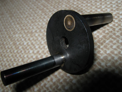
...But it didn't stop me doing some work on the Ketro KT120fst engine. I've not been satisfied with the design of the crankshaft where two M3 grub screws hold it all together. So I've come up with a design modification that will beef up the strength and rigidity. I made two special screws from M4 cap head socket screws and I turned off a section of thread to form a 3.0mm dia. pin whilst leaving a threaded section intact. Then I drilled and reamered a 3.0mm hole through where the original M3 thread was in the crankshaft parts, followed by an M4 thread down to the center, and counter bored 6.0mm dia. to contain the screw head, which incidentally, I turned down to size. Now I have far more confidence in its integrity.


More integrity
You can see the screw head in one crank and the pin in the other. Unfortunately there is a little bit of run out along the length of the shaft, but I'm hoping the rear bearing set will contain it.

Sunday, 15 November 2009

I went flying today.

The weather this week has been appalling with heavy rain and gale force winds at times. Today, it was superbe with sunshine and light cloud and light winds. A day not to be missed. Tomorrow is forecast to be back to heavy rain and gale force winds.


Jamies Bobcat now fitted with larger Jetcat P80se

Saturday, 14 November 2009

The Front Housing and some assembly

Well, just enough to see if it fits. I made the Front Housing and fitted the crankshaft and conrods together in the crank case. 'Tis at this point I've discovered I need to remove a very small amount of material from the bottom of the sleeves because they foul on the crankshaft. Oh! well I can't see it making any difference to performance other than it just makes the engine that little bit lighter. Every little helps.

Here's some pix:-


Front Housing in the lathe for final machining


Note how its bolted to the mandrell


The rear end view


Assembled (temporarily)

Next will be the gudgeon pins and the PTFE end pads to prevent the gudgeon pins from scoring the bores. Then I can get the pistons moving.

Sunday, 25 October 2009

Some engineering works

As I haven't blogged for a while, especially on engineering, I thought (careful) that I'd make an update. I've finished the inside of both cylinder heads today leaving just the ports to do, and to give an idea of how far I'm ahead (or behind), I've taken some pix of everything.


Using a boring bar to form the valve seats

Crank case, cylinders and liners


Pistons and valves


Cylinder heads, port and starboard


Crank shaft complete with conrods and bushes


Preparing for finish machining

Saturday, 26 September 2009

The best conditions...

...for flying today. Jim flew his Mig, Ian flew his F16, I flew the Yak, and Brian flew his Piper Pawnee. The weather was so good, I managed a couple of flights with the Ember.


Brians Piper Pawnee
Brians Piper is a nice model, built from a Hangar 9 kit, its an ARTF powered by an OS 52 fs four stroke engine and guided by Spektrum 2.4 Ghz radio.
Ians F16 was impressive, together with smoke system, he has afterburners in the tail pipe. Actually, its an array of ultra bright LEDs switched on by a micro switch at 3/4 throttle and above. Had me and Jim fooled as there was some flames exiting the tail pipe on start-up, so we thought it was alight while it was flying.
There was a lot of microlight activity today, this is a particular menace to the jet pilots as jet aircraft use up so much airspace. Microlight pilots don't seem to be aware of the dangers of flying through our airspace. A record of the number of movements was taken today.